I'm going to cover the general LED build with the first fixture for anyone looking to get their head wrapped around the way they work. They are really easy once you get the idea. In future fixtures after this one, I'll forgo the soldering and such...
First up is the Refugium/Sump LED Light. I'm using:
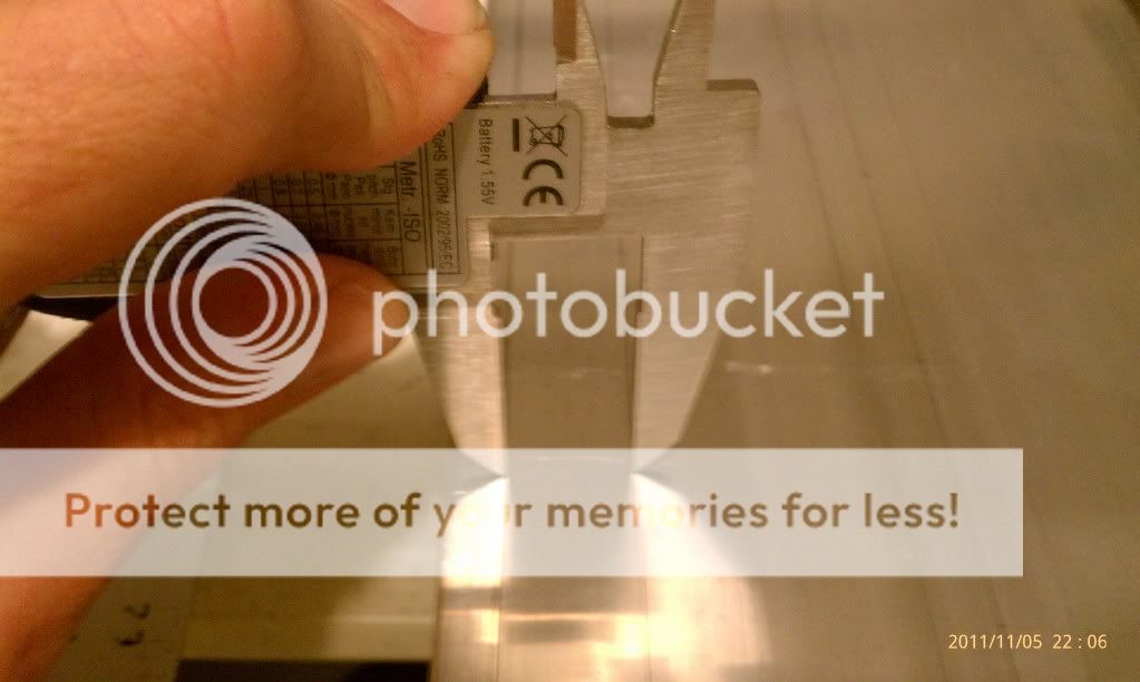
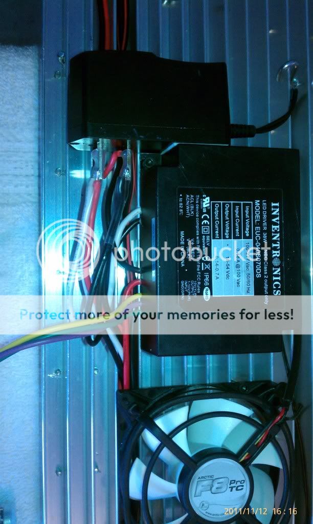
1- Inventronics 1050mah - 36v dimmable driver. (reefledlights.com)
10 - Cree XP-G Cool White w/ 80 degree optics. (rapidled.com)
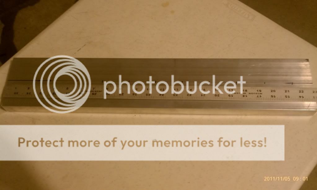
1 - 4.23" x 23" Undrilled Heat Sink (rapidled.com)
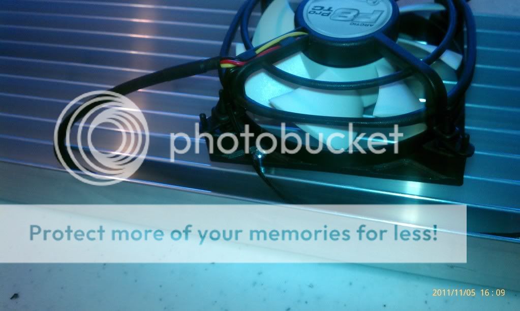
1 - Arctic Cooling F8 PRO TC ARCTIC F8 PRO TC 80MM 500-2000RPM FAN (platinummicro.com)
1 - Thermal Paste (enough for just about my whole build) (rapidled.com)
1 - 2 prong cord (lowes)
1 - 12v dc adaptor (altex.com)
I'm replacing a 96 watt quad c.f. fixture (had it for at least 6 years, or about 8 bulbs). The new LED adds up to about 30watts.
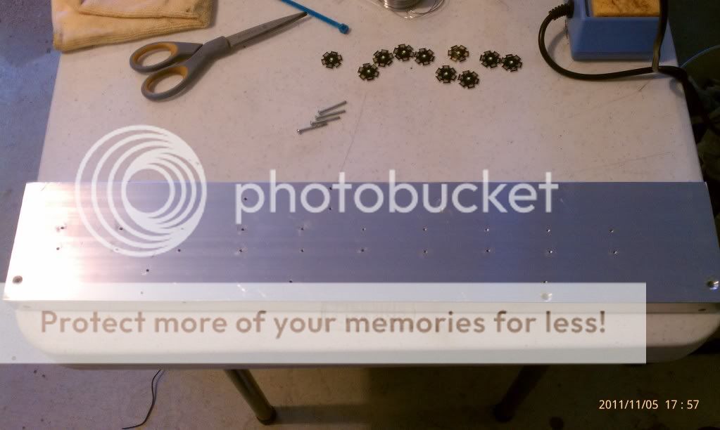
Here is the Heat Sink being marked out. I used a sharpie marker to mark the locations of each star.
The distance between the holes is 3/4". So I used a set of calipers to mark the aluminum. Lock them at 3/4" and it is easy to gently push the tips of the calipers down and make a center mark for each hole. The drill bit will center off the mark when you go to drill.
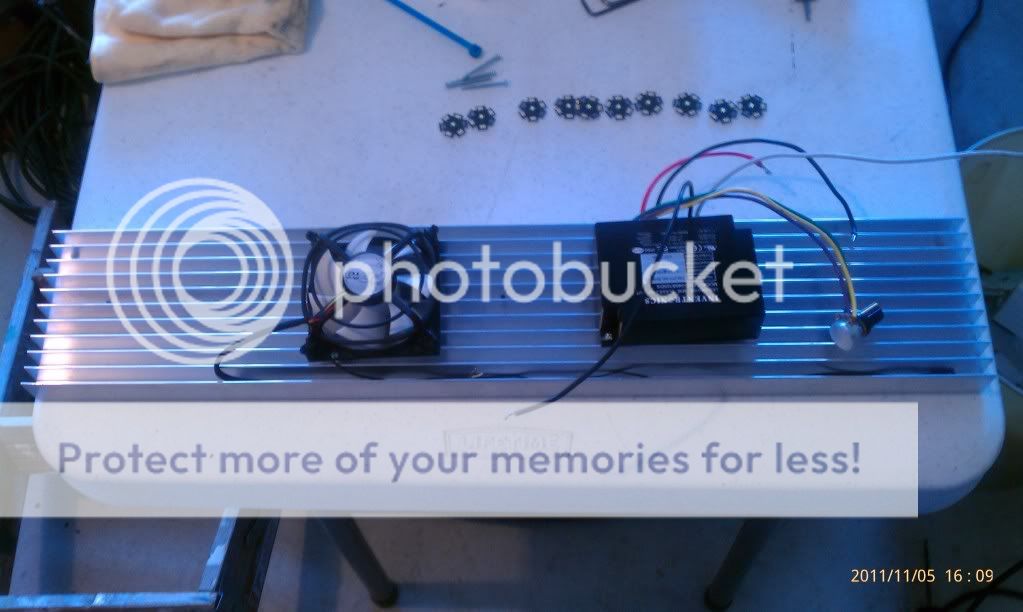
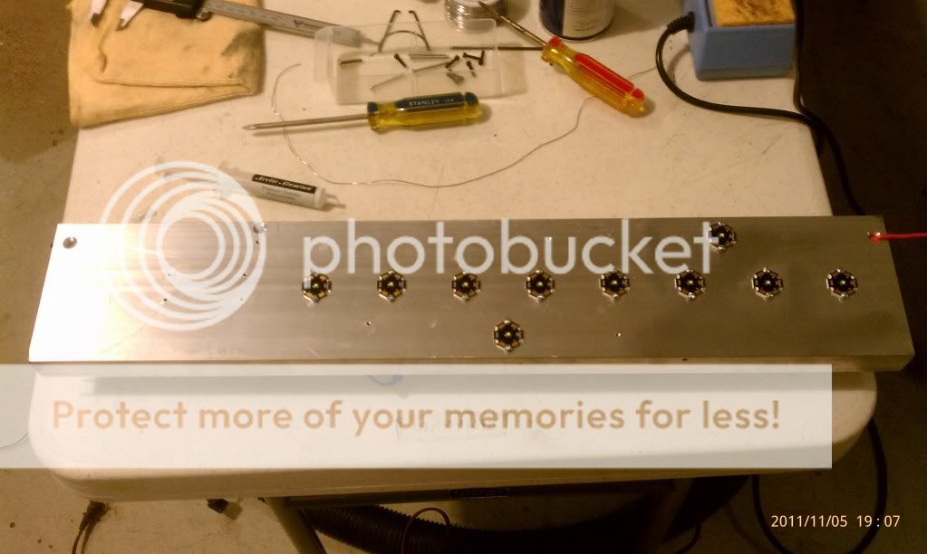
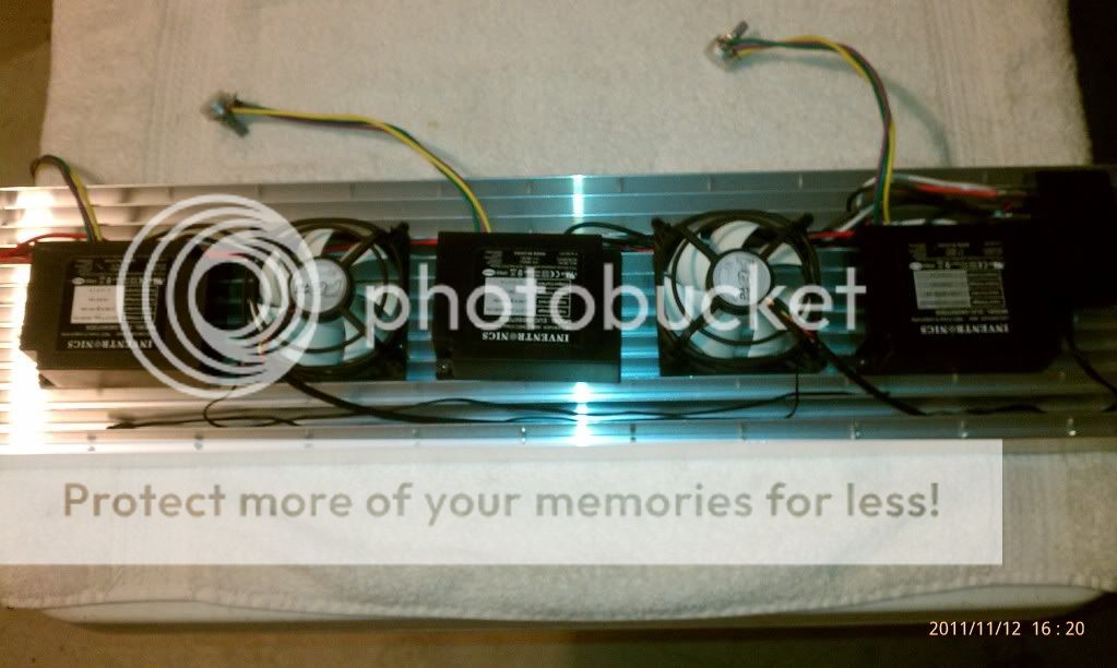
Take the driver and fan and lay them out on the fins. I placed them evenly with about 5" between them and marked the hole locations for the mounting flanges. (next 2 pics) You have to drill down between the fins. I made sure the holes were clear of any Crees on the other side.
I used 1-1/4" screws. (lowes)
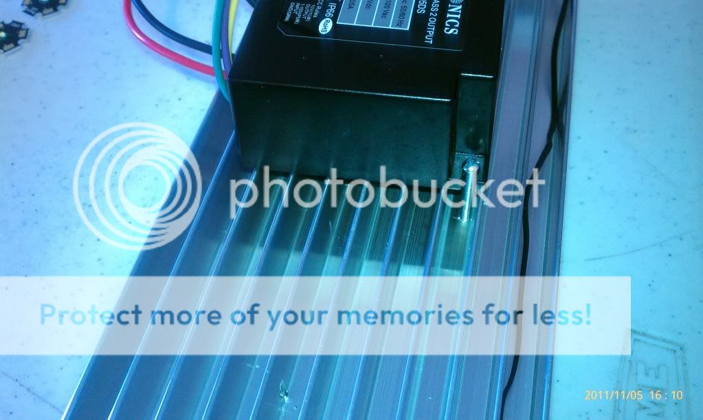
Here it is drilled and tapped. I have a small press from lowes that handled this well. If you make sure your holes line up so they don't hit the fins, you will have a better chance with the taps. Go slow! I drilled 1/4" holes for the main wires and beveled them with a chamfer tool. You can use a 1/2" drill bit and accomplish the same thing.
Here the Crees are screwed down. I used thermal paste. Since I'm pretty much going down the heat sink, it works out nicely that they all face the exact same way. I used thin plastic washers for insulation. You can see the chamfer on the main wire hole too.
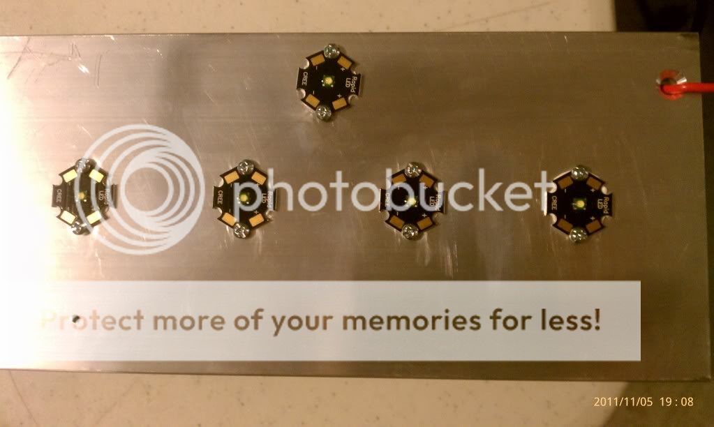
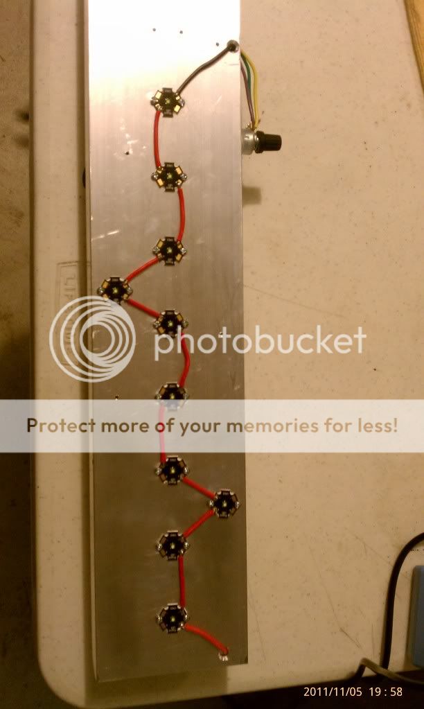
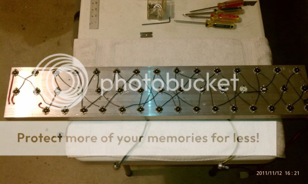
This is the layout for the Crees. I intentionally bought a longer heat sink than needed. (I'll be making a 24" enclosure), so the pattern runs down longer than needed for now. You will see my sump/refug later.
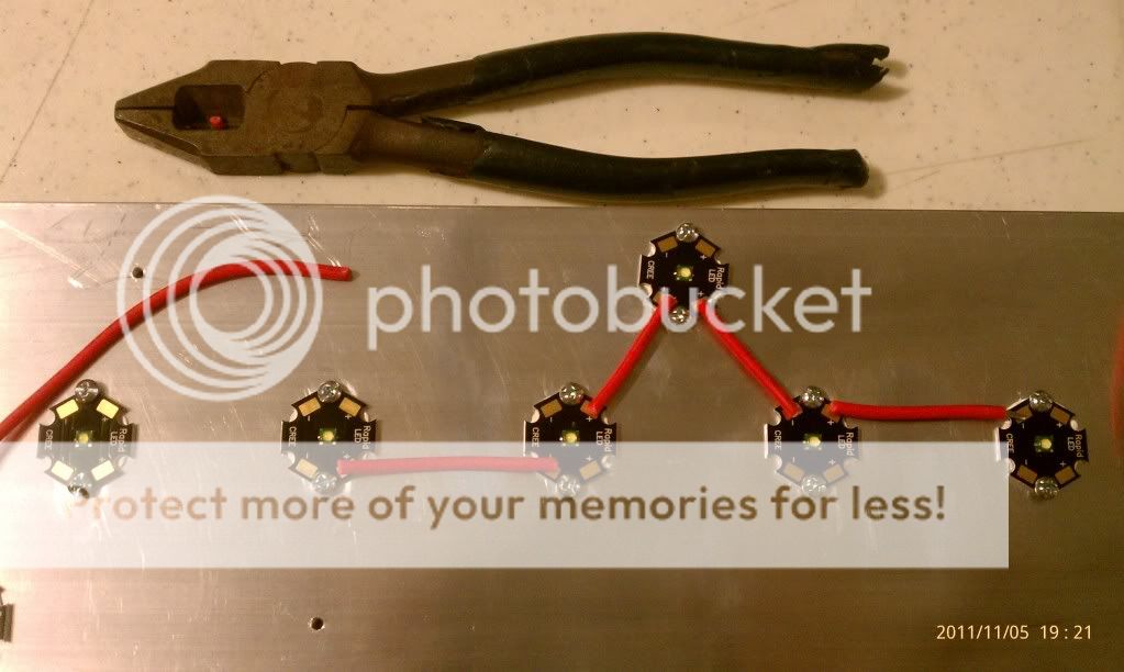
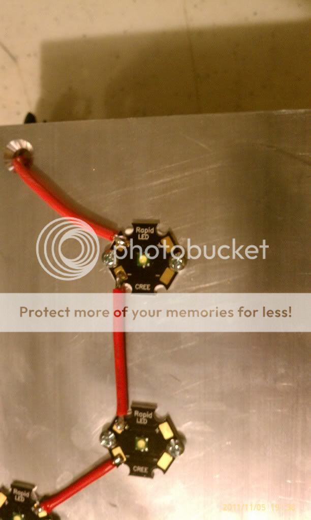
Off to cutting wire. I cut them just long enough to cover the gold solder patch. You go positive to negative and repeat. Easy pattern to alternate sides.
I like this nifty wire stripper. Makes the job much faster. Visit altex.com $10.
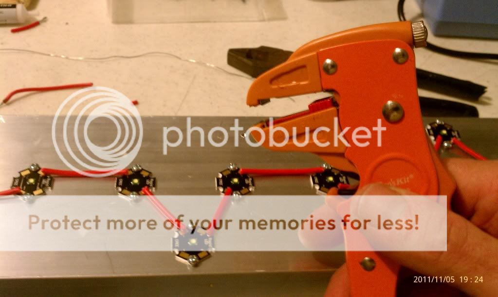
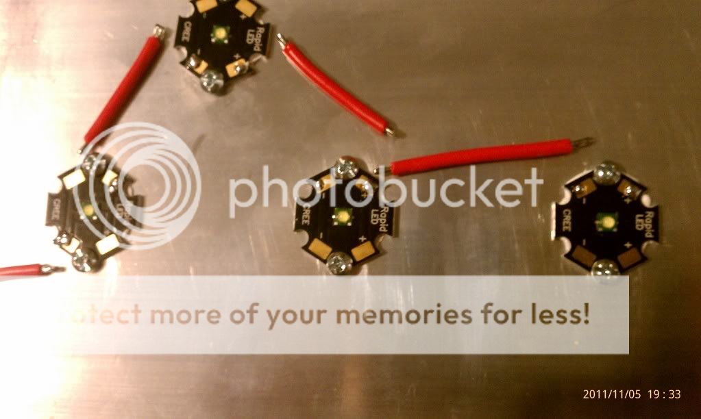
Here the wire is stripped and tinned. I also tinned each star. I bought a small solder station from altex for $22 thats working very well and has a pointed tip. You can see where I actually tinned just the corner of the gold solder patch.
Solder them in! Keep the solder nice and shiny. Great solder iron!!
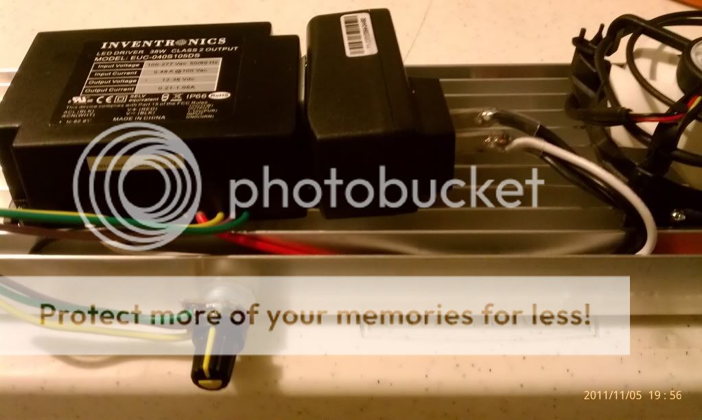
Here they are all soldered in. I have the driver mounted on the other side so the main wires stick through to complete the loop.
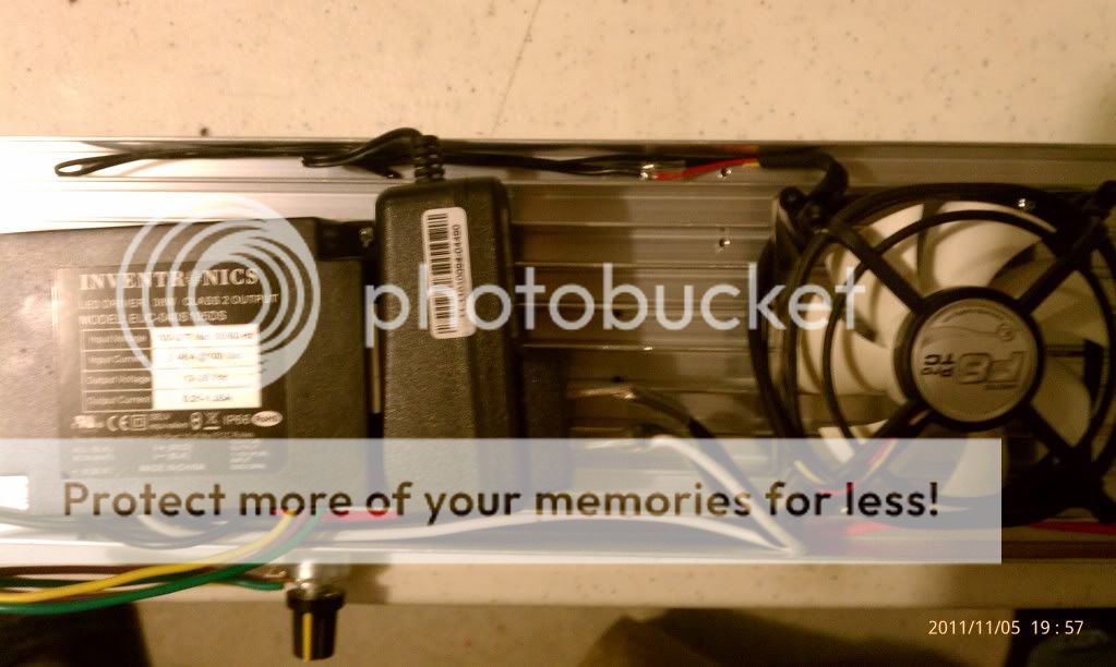
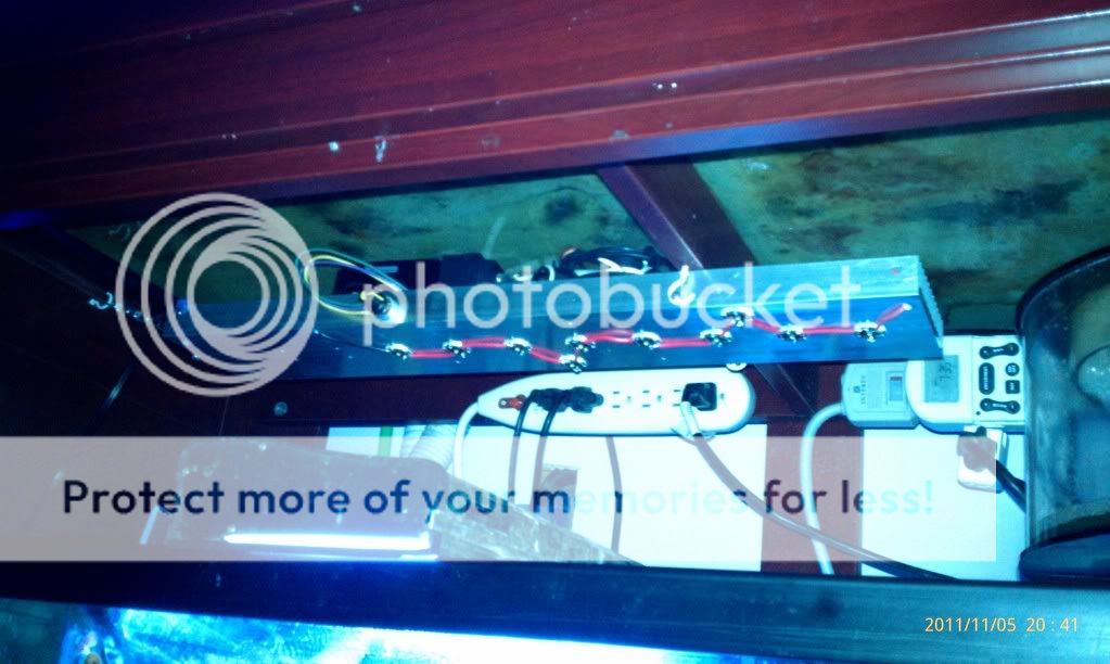
Here is a view of the top lay-out. The driver and fan are screwed into place. I used a 12v wall adaptor from altex and double sided taped it to the driver with some of that 'make sure its in the right place tape'. I used the outlet prongs off that as a bus bar for all the ac power. The main power cord runs to it. And the driver ac input lines run to it. The fan is connected to the output from the 12v adaptor. So when you plug the one cord in, all comes on. I used clear heat shrink so the connections are easily checked. And I made sure the heat shrink covered the prongs of the adaptor completely in the event it comes off.
Here is another top view. You can see that the wire will nestle in the fins nicely. You could take double sided tape and wedge a square down to hold the wire more securely. You can see the fan wired in here. And I double side taped the dimmer on the side of the heat sink.
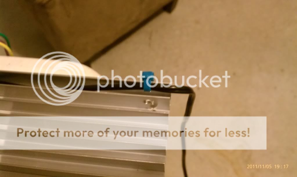
I hand drilled the side fins to zip tie the power cord onto the heat sink.
One last check that everrything is wired right....
AC Power - check,
Driver AC power - check,
Driver output Red going to + on first Cree - check,
Crees going positive to negative to positive to negative to 8O - chack,
Driver Black wire going to - on Cree - check,
Fan wired red and black correctly - check
Everything Heat shrinked and secured to the Heat sink - check
Let there be light!!
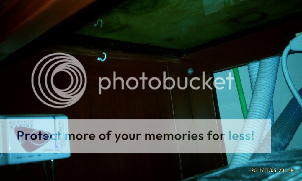
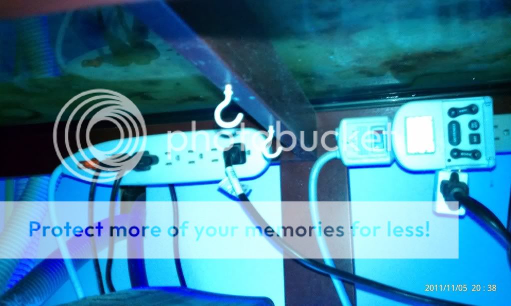
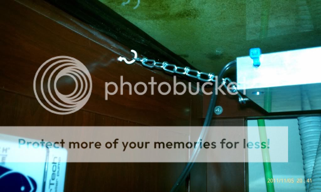
Now to hanging. I drilled and tapped (3) 6-32 holes into the side of the heat sink. I made sure they went into the bottom material. You will see them shortly. Here, I measured the inside of the sump area and screwed these eyelets in.
These are about 5" apart. So the heat sink goes between them in this set up.
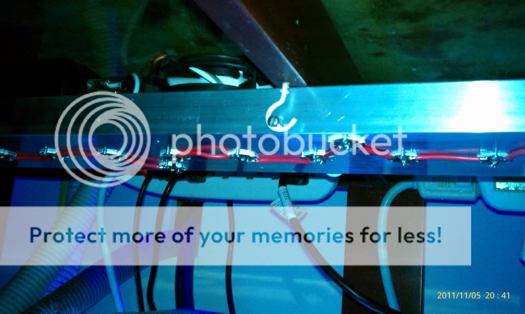
Now a couple of pics with it installed and I think you will get the idea. I used 1" 6-32 screw so I had some room left to right.
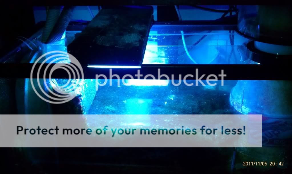
Mounted in place.
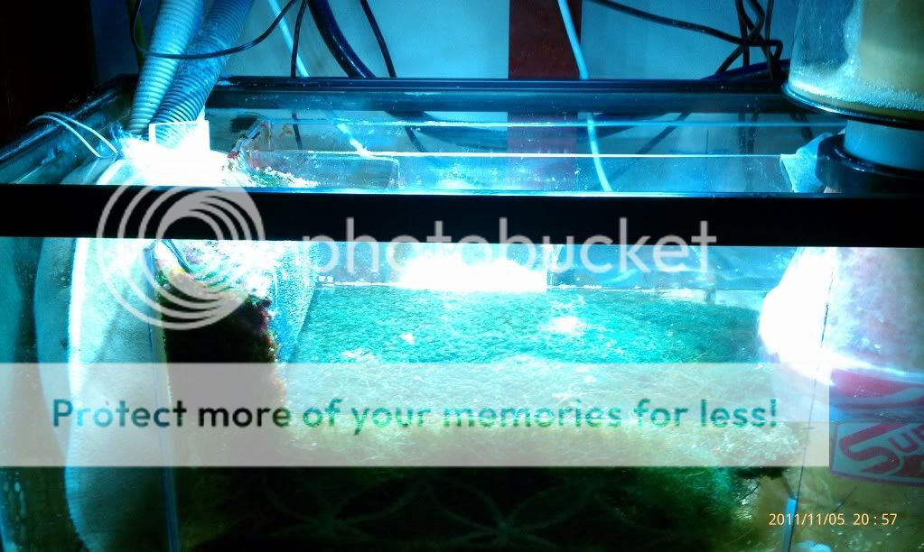
Now to the important stuff..... is it enough light...
Here is the before pic with the 96 watt fixture...
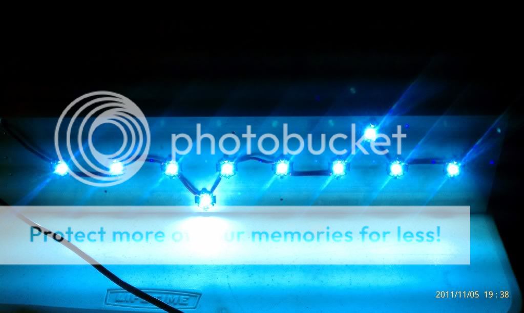
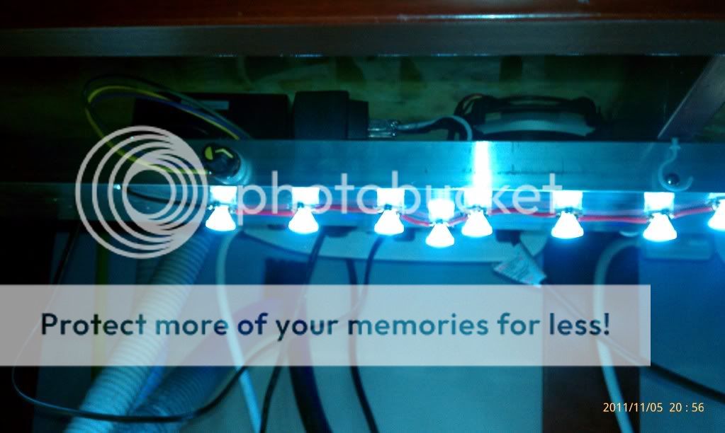
Here is a pic of the LED Fixture...
And a pic of the LEDs turned all the way down....
One last pic of the fixture on and in place....
So it looks like there is a much improvement in light with the leds turned all the way up. If I had used a 700mah driver, it might have been around the same. If your looking for the cheapest way, a non-dim 700mah driver pushing the 10 Crees would be just fine for a sump/refugium. It will be interesting to get the killawatt and measure the energy difference. I'll get that tomorrow...... Any questions up to this point? Enough Pics?